Giraganci – Hooks Turner
MAIN FEATURES
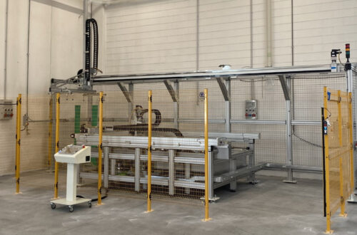
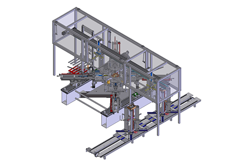
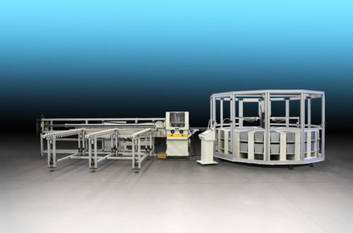
Giraganci – Hooks Turner is a machine for the assembly of picture frames with the back panel. It is made of 5 stations:
a robotized workstation for fixing the back panel by rotating the appropriate hooks, two manual work stations upstream, other two downstream for storing finished pieces.
Loading Zone
The first and third stations are used to operate manually and consist of a series of conveyor belts with a 30° inclined work plane to make the workstation ergonomic. Each conveyor belt is equipped with an asynchronous motor and an inverter to vary the speed (max speed 0,3 m / s). To facilitate the support and the sliding of the pieces on the inclined surface, the lower edge has a small belt of about 20 mm in height that moves at the same speed as the main conveyor.
Working Area
The automatic work station floor consists of a conveyor belt 1450 mm long, 800 mm wide, equipped with an asynchronous speed variator motor with inverter (max speed 0.3 m / s). A robot (3-axis Cartesian + 1 rotary for the clamp) turns and fasten the hooks into the frames.
Axis x: 1000 mm stroke , Brushless motor 400W, 1 m / s speed;
Y axis: 800 mm stroke, 100W Brushless motor, 1 m / s speed;
Z axis: 150 mm stroke, 100W Brushless motor, 0.25 m / s speed;
R axis: (rotary) stepper motor with encoder, 2500 deg / s speed;
The Vision System
A vision system (equipped with camera, lighting system, PC and monitor) detects the positions of each hooks and provides the robot with the coordinates (X, Y and rotation angle) to drive it during machining.
Each hook can have a random orientation and (as can be seen from the processed image) it must be rotated in one direction or the other depending on the side of the frame in which it is located.
The frames can be of various sizes, of different colors, different thicknesses, with a variable number of hooks which could have different heights.
Therefore a sensor accurately detects the height of the panel both to guide the z axis of the robot and to correct the values of the x and y coordinates that change according to the height of the piece, since the optic of the camera is positioned above the working area.
The correction and processing of coordinates task is done thanks to a special algorithm developed by our technicians.
The measurement takes place in the center of the frame after the camera has determined its size to avoid the reading of the Z sensor from being distorted by a hook or frame since the picture frames are of various sizes (green cross in fig.2)
The lighting system
The lighting system consists of a series of LED lights positioned around the camera that are able to attenuate the effect of shadows or reflections and to highlight the contour of the details to be detected. Furthermore, to avoid the influence of lights from outside, the entire detection area has been enclosed in a darkroom.
A series of rollers, with freewheel type bearings, controlled by two electric axes, ensure the guide and the maintenance of the picture frame during processing, adapting to its dimensions.
Unloading area
A conveyor belt with variable inclination, provided by a pneumatic cylinder, performs the function of interface between the horizontal belt of the automatic station and those of the manual stations which are inclined by 30°.
A series of photocells sends the information to the PLC which provides to regulate the flow of the panels on the 5 conveyor belts.
The control panel includes a PC with a 17″ Touch screen and the relative electrical panel, and allows to control and check the functionality of the machine:
- starting and zero axis
- input / output control
- alarm control
- picture frame selection and automatic cycle start
- control of meters and bypass stations
- image control detected by camera.
Particular attention has been paid to safety: the robot operating area is not accessible during machining because it is completely enclosed in a casing that can be opened through two windows controlled by a safety switch. The other moving parts, motors, fixed and self-moving conveyor belts, are protected by fixed guards made of 3 mm sheetmetal or polycarbonate.
Characteristics of work pieces
- Frame size: min 100 x 130 mm, max 800 x 600 mm
- Panel thickness: from 2 to 3 mm
- Panel height from the worktop: min 10 mm, max 45 mm
- Dimensions and shape of the hook to be rotated: 16 x 55 mm thickness 0,3 mm with hole ø 4 to 8 mm from the rounded end and fold of about 30 ° to 14 mm, tooth thickness at the opposite end 1,5 mm., max height of the tooth before insertion about 20 mm (see attached photo). Surface treatment: white zinc coating
- Height and slot depth of insertion: 3.7 mm x 5 mm
- Position of the hook before insertion: approximately 42 mm from the edge of the panel and at an angle between 0 and 180 °towards the frame direction

Operating
An operator manually places a frame on the first conveyor belt and activates the foot control for the passage of the piece to the next station.
The transfer from one station to another takes place automatically, provided that the operation is completed and the next station is free.
The fourth station is a conveyor belt with variable inclination, which allows the passage from the third station inclined at 30°, to the fifth that is located horizontally.
The fifth station is completely automatic: the frame is carried by the conveyor belt against a self-propelled bar and then laterally closed by a roller conveyor driven by two electric axes. Once the frame is in position, the camera performs the shot and sends the images to the PC which first determines the center of the frame and then the coordinates (x, y and a) of each hook.
Then the robot positions itself above the center of the panel to allow the sensor to read the Z coordinate, the data are processed by the PC which then drives the robot.
The robot moves over the first hook, makes it lower and turn to close the panel, the operation is then repeated counterclockwise on the hooks to follow.
Once all the hooks have been closed, the stop bar is raised, the side roller conveyor opens, the conveyor belt provides to evacuate the worked panel and to receive a new one.
The design of the mechanical part, the electrical panel, the PC software, the PLC and the vision system, as well as the realization of the mechanical parts and their assembly is the work of our company technicians MAC.MO. srl : Paccagnella Tiziano, Pagiaro Mario, ing.Alberto Rosso.
Contact us for further informations!