205 FOR-X5 & Plastline2
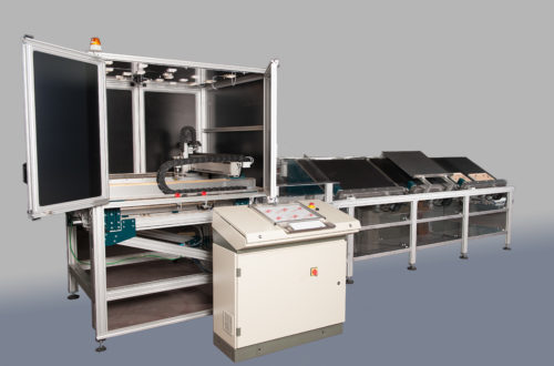
The FOR-X5 & Plastline2 is a system for cutting and assembling frames for paintings or mirrors, controlled by an industrial computer that controls 16 axes equipped with Brushless motors, 10 DC servo drives for service movements and various I/O controlled with Ethercat protocol. A graphic monitor with 12″ touch screen allows you to control any manual or automatic movement of the system, check the operation of all processing phases and set or memorize the cycles and work programs.
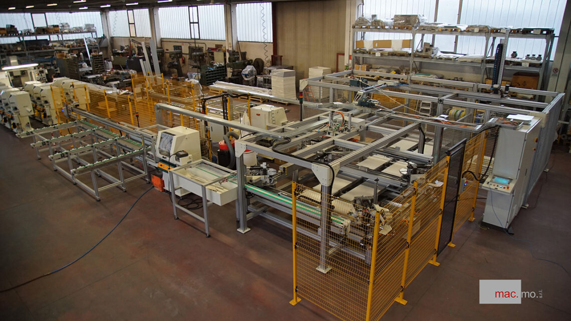
The system is made up of:
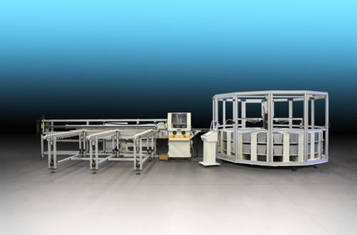
A –N.2 Plastline automatic cutting machines, each with its own rod loader, which feed the assembly machine. Both miter saws are equipped with 2 circular blades (HM Ø 350) for cutting at 45° + 45°, a drilling unit and a milling unit for disc tool of size. 205 x 6 mm which allows the processing to be carried out
B – The For X5 assembler for joining corners using steel staples, it consist of up of four staple heads adjustable directly from the operator panel, 2 transfers for loading the pieces to be assembled, 1 transfer for unloading the assembled pieces and a treadmill for evacuating frames.
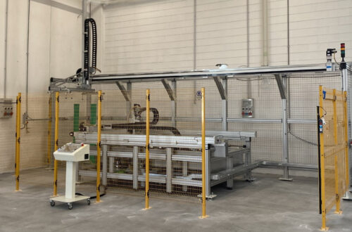
C – A three-axis transfer system, which takes the finished frames from the conveyor belt of the assembly machine and stacks them one on top of the other, rotating them alternately by 90°, in two stations located on the sides of the treadmill itself.
Dimensions of the frames to be produced: max 1700 x 1700 mm, min 400 x 400 mm
Sections of the rods to be machined: max90 x 50mm
Length of the rods to be machined: max 5000 mm min 2000
Surface area occupied by the system: 13 x 8 m
Miter saw storage capacity: 20 + 20 rods
Output warehouse capacity: 60 + 60 finished frames (h 25 mm)
* * *
The FOR-X5 & Plastline2 works quickly, unattended, allowing you to reduce the production costs of the frames; the operator’s intervention is limited to loading the rods to be machined and removing the finished frames. In detail:
- to load the rods on the two loaders of the cutting machines, on average 2 min x 20 rods, 4 min for both loaders. The machine will take approximately 14 minutes to empty the two magazines for a 1500 x 800 frame, the operator will be busy for 28% of the machine’s operating time.
- staple loading approximately takes 5 min every 5000 frames, approximately every 6 hours, 0.3% of the operating time.
- emptying of the two outgoing warehouses approximately 2 takes minutes to replace two full pallets with two empty ones every 140 frames, approximately 50 minutes. (4% of operating time).
On average, therefore, the time needed to carry out these operations does not represent more than 33% of the operating time at full capacity.
* * *
DESCRIPTION OF MACHINERY
A – Plastline automatic miter saw is an electronically controlled machine, equipped with 2 circular blades (HM Ø 350) for the simultaneous cutting at 45° + 45° of rods for frames made of wood, plastic or similar materials.
Using the control panel, it is possible to set the quantity and dimensions of the frames to be cut, as well as any recovery measures for the piece at the end of the rod; the work cycles can be stored and recalled when necessary.
The machine is equipped with a linear axis with a useful stroke of 5000 mm, controlled by a Brushless motor, which advances the rod to size. At the exit, a gripper on a pneumatic axis transports the cut pieces onto a treadmill which evacuates them. The combined movement of these two axes allows for, for some measurements, “relay” cutting to be carried out, that is: the feeding gripper delivers the piece to the unloading gripper which moves it by a fixed amount to trim it from the other side. In this way it is possible to exploit the rod in its entire length and avoid rejects.
The downward movement of the blades is produced by a pneumatic cylinder and, as an optional (Opt.3) it is possible to have an electric cylinder assisted by a Brushless motor which drives a recirculating ball screw. In this way, compared to the traditional pneumatic cylinder, a constantly controlled speed is obtained, a movement perfectly synchronized with the piece advancement system and therefore a better productivity and cutting quality.
The machine is equipped with a feeding magazine, arranged horizontally, capable of accommodating up to 30 rods, which are withdrawn from time to time until completely exhausted. The dimensions of the rods that can be worked:
– length 90 mm
– height 50 mm
– max. length 5000 mm
– min. length 2000mm
Dimensions of the machine without outgoing finished parts warehouse:
– length 2500 mm.
– length 6000 mm.
– height 1700 mm.
The machine is equipped with suction ports for connection to the centralized vacuum system and a conveyor for waste pieces of such dimensions that they cannot be evacuated with the suction system.
Power supply: 3.3Kw at 400V/50Hz
Pneumatic supply: 6 bar, consumption300 l/min. (100 l/min with Opt.3)
* * *
B – FOR-X5 has no. 4 joining heads, equipped with a gauge, adjustable clamp and crimping unit with staple feeder which, in normal operation, allows an autonomy of approximately 30 hours. The metal staples can be of different heights, 6-8-10-12-14 mm and are easily interchangeable.
As an optional (Opt.5) it is possible to adopt crimping groups with coil crimping, type NR (10000 pcs. for sizes 12-14-16 mm, 15000 pcs. for sizes 5-6-8-10 mm, 20000 pcs. for 4 mm.)
The crimping unit is controlled by a Brushless motor with positions and quantities of staples that can be selected and memorized via the control panel.
The For-X5 is equipped with three transfers controlled by brushless motors and pneumatic cylinders:
- the transfer 1st transports a long and a short piece, coming from the cutting machine 1, to the assembly area,
- transfer 2nd, at the same time as the first, transports a long and a short piece, coming from the cutting machine 2, to the assembly area,
- transfer 3rd picks up the assembled frames and places them on the exit conveyor belt.
Their speed is adjustable and can reach up to 2 m/s. This allows the transfer of pieces in times of the order of fractions of a second.
The work cycle consists of the following phases:
a – Transfer 1st picks up the long piece arriving from cutting machine 1 and it positions it in the assembly area, parallel to itself.
b – At the same time, transfer 2nd picks up the long piece arriving from cutting machine 2 and it positions it in the assembly area, parallel to itself.
c – Transfer 1st picks up the short piece arriving from cutting machine 1 and positions it in the assembly area, rotated by 90°.
d – At the same time, transfer 2nd picks up the short piece arriving from cutting machine 2 and positions it in the assembly area, rotated by 90°.
e- four squares tighten the frame
f – the upper clamps descend onto the frame and the staples unit takes care of the union by inserting the metal staples in several positions, even one after the other, according to what is programmed.
g – the clamps and squares return to the rest position, the four heads move back and the frame is picked up by a cross support controlled by a pneumatic cylinder (III) and placed on the conveyor belt below, which will take it to the exit warehouse. As soon as the joining area is free, the transfers (1st and 2nd) will immediately take the pieces for a new frame to be joined.
On the For-X5, performing the format change is simple and takes a few minutes, just:
1) set the dimensions of the panel to be processed on the operator panel;
2) adjust the positions of the stops to the size of the pieces coming from the miter saw, enter the position of the measurement stops operated by servomotors in the control console;
3) adjust the position of the gripping suction cups;
4) adjust the position of the exhaust suction cups;
5) position the upper pad of the seaming unit;
6) type the quantity and position of the staples on the control panel;
– Dimensions For X2: 4,200 mm. width; 2,500 mm. max. height; 4,100 mm. max. depth
– Weight For X2: approximately 650 kg.
– Max. dimensions workable rods: 90 mm width. and 50 mm. height;
– Max. frames dimensions: 1700 mm. x 1700 mm. (external measure);
– Minimum dimensions: 400 mm. x 400 mm.;
– Approximate hourly production for medium-sized paintings with two staples per corner: approximately 300 frames/hour;
– Processed frames warehouse capacity: 70 pcs. x 2 (25 mm thick)
– Electrical power supply: 400 V three-phase + N, 3.5 KW;
– Compressed air supply: operating pressure 6 bar, consumption 400Nl/min.
* * *
C – A three-axis transfer system, located at the end of the conveyor belt, it takes the frames coming out of the FORX-5 assembler and it stacks them on pallets placed on the sides of the conveyor belt itself. Each frame will be rotated 90° compared to the previous one, to prevent the staples from scratching the visible part and to facilitate the insertion of the cardboard protective corners. A sensor system will detect when one stack is completed, so the transfer will work on the other. When both stations are about to be filled, a light signal will alert the operator to avoid stopping the plant.
Contact us for further informations!