ALULINE & ALUSTEP 172
For large production of ventilation grids
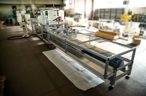
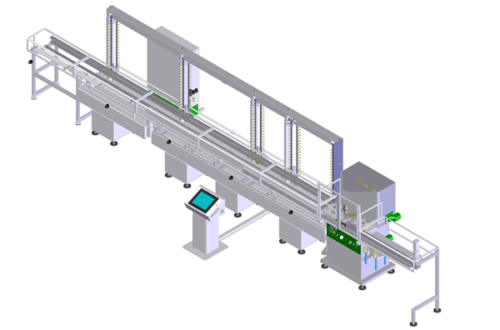
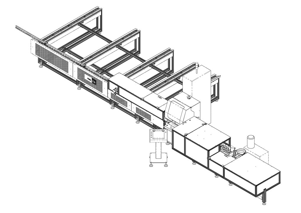
Aluline & Alustep 172 – Automatic line for cutting, punching and bushing inserting on aluminum profiles
ALULINE & ALUSTEP 172 is an automatic line for the production of ventilation grids frames.
Aluline 172 is an Automatic Double Miter Saw for 45°+45° V-cutting on aluminum profiles for ventilation grids frames with horizontal loading warehouse. Connecting it with the automatic device Alustep, it makes it possible to produce frames cut to size, with three different kinds of punching shapes and the insertion of plastic bushings.
ALULINE 172
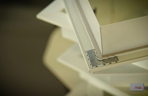
Aluline 172 Automatic Double Miter Saw is an electronic control machine, it is equipped with two circular blades (HM Ø300-350) V-cutting of thin-walled aluminum profiles (like the one shown in the figure below) , max length 6000 mm; min length 1200 mm.
Cut Pieces length: max 1200mm., min 100 mm.;
The circular blades Ø300 or Ø350 rotate at 3600 rpm and move vertically cutting the rod. The rotation movement is powered by two engines of 2.0 kw of power at 3600 rpm.
A pneumatic cylinder (diameter 80mm and a stroke of 275mm) performs the vertical movement.
The machine is equipped with vertical and horizontal pneumatic clamps and a system of interchangeable supports suitable for the profiles to be cut.
All the pipes are protected with metal mesh sheaths to prevent accidental projection of scraps and pieces of aluminum from damaging them.
A 12” control panel allows an easy setting of the work cycles and a total control of all the parameters and functions of the machine.
The horizontal loading warehouse allows a comfortable, quick load and it can be executed in total safety even with the machine running.
The feed system is “walking beam”, it can accommodate up to 30 rods and it is equipped with the necessary devices to correctly maintain the profiles.
Rods min length 1200mm; max 6000mm.
On request, the automatic loader can be equipped with a trolley to support a bundle of rods which further facilitates the operator during the filling phase of the warehouse.
Aluline 172 is equipped with a linear axis for the advancement of the piece powered by a Brushless motor, useful length 2000 mm capable to advance rods 6000 mm long in three or more steps. The clamp is equipped with the devices necessary to correctly maintain the profiles
An unloading linear axis , powered by a Brushless motor, extracts the cut pieces to take them out to the unloading tray (cutting option only), or to pass them to the subsequent machining operations (cutting + punching and inserting bushings option).
Relay Cut
An important function performed by the unloading clamp is the recovery of the rod end part through the “relay cut”. The rod is passed from the loading clamp to the unloading one which will perform positioning for cutting to the desired size. In this way the whole rod can be exploited along its entire length and the waste is considerably reduced. It can be ZERO if well programmed.
Disintegration
Another task performed by the unloading clamp is the waste disintegration. Aluline is able to automatically choose to chop into small pieces and evacuate the discarded part of the rod end remaining as a result of the relay cut , for those measures too small to be unloaded and too large to fall normally in the central waste discharge, thus avoiding any jam problem due to the possible wrong separation of the rod end residue.
A sprinkler system (one for each blade) of lubricating cooling fluid that is adjustable in the flow rate and delivery time ensures correct cutting operation.
Aluline & Alustep 172
ALUSTEP
ALUSTEP allows you to perform three different types of punching and the insertion of plastic bushings on the profiles coming out of Aluline. It is equipped with two controlled axes (X and Y) and therefore the position and quantity of the holes can be precisely selected by the operator via control panel.
Alustep features:
a – a movement system for gripping, orientating and shifting the pieces coming out of Aluline 172
b – three punching units controlled by hydraulic cylinders: the first one normally used for the seat of the “intermediate” element, the second one for the seat of fins for the air intake grill, the third one for the hole for housing the plastic bushings
c – Bushing Insertion Unit
d – three position conveyor tray to select and send the workpieces into three different zone depending on the work performed.
a – the movement system consists of 3 phases:
1a – Transfer 1 takes the piece from the unloading axis, it moves it away from the Miter Saw machine through a system of clamps and pneumatic slides.
2a – the piece is rotated 90 ° outwards if it does not need any other work and must be unloaded, or inward if it must continue for punching and bushings insertion (if programmed).
3a – Transfer 2 takes the piece with a system of suction cups, mounted on two controlled electric axes, orthogonal to each other, it positions it and makes it advance step by step under the work stations, as programmed.
In order to optimize and reduce transfer times from one phase to the other, the pieces can be stationed in each of the transfer systems until the one downstream is freed. The cut pieces that do not require further processing come out of the bypass tray by turning the transfer 1 outward.
b- The punching station is equipped with n.3 hydraulic punching machines with steel structure, suitable to make a hole with a maximum surface area equal to the area of a circle with a diameter of 10mm, on sheet metal and profiles with max thickness 3 mm. The units are provided with a punch holder cylinder, inside which there are springs for extraction; the matrix is of such a height that it is possible to machine L-shaped profiles. The units are complete with 40 mm bore hydraulic cylinder which allows punching in the order of 0.2 sec on the long side of the L-shaped profile up to 7.65 mm from the joint with the short side. The hydraulic power unit is equipped with flexible hydraulic pipes (allow positioning about 1.5 m from the punching unit) and oil collection tank.
c – The Bushing insertion unit is equipped with a vibrator that distributes the plastic bushings and orders them on a firing channel. Here a pneumatic cylinder provides for insertion into the profile holes. This Unit is positioned at about 200 mm from the circle hole Punching Unit, it is powered by Transfer 2 and it is automatically activated, if programmed, as soon as the previously executed hole is in the correct position.
The function of punching and bushings insertion can take place simultaneously on the same piece, allowing to reduce the processing time by half
OPERATING
The use of the machine is very simple. Via Control Panel, the operator will have to insert a program for each piece he wants to realize and indicate:
– piece length
– The position of the unloading warehouse.
– The position (x, y) and n. of repetitions of the holes for the first, the second and / or the third punching machine;
– By choosing the “bushing” function, the machine will automatically punch and insert the bushings on the pieces.
Once the programs relating to the individual pieces have been edited and saved, they can be recalled from the production program, in the necessary quantities in series for the optimization of the lengths of the bars to be cut to obtain the least possible waste.
INDUSTRY 4.0 PLAN REQUIREMENTS COMPLIANCE
Auline & Alustep 172 machine is able to meet the requirements of the Industry 4.0 plan and be able to take advantage of the tax benefits provided.
The control system ensures:
- Interconnection: The industrial PC (* optional) makes it possible to control, monitor the machine remotely and monitor production data, interacting with SQL and MySQL databases by querying tables (queries) via FTP or shared folders. It can read text files with processing lists and at the same time make available all production data, any alarms and machine states.
- Integration: it can communicate with other machines using:
- fieldbus standard (Modbus, Modbus TCP or Ethercat optional*)
- proprietary protocols, based on ethernet or serial.
- Interface: the touch-screen operator interfaces satisfy the criteria of simplicity, intuitiveness and portability on various operating systems.
- Compliance: this criterion is satisfied in the Machine Directive (CE marking)
TECHNICAL SPECIFICATIONS
| Aluline Weight: | 820 kg |
| Alustep Weight: | 380 kg |
| Aluline Dimensions: | length 7118 mm; height 2270 mm; width 2153 mm; |
| Alustep Dimensions: | length 3522mm; height 1162 mm; width 1600 mm; |
| Power Supply: | 380/220 V three-phase; 10 kw |
| Pneumatic Supply: | pressure 6 bar; consumption about 200 nl/min |
| Tools: | circular blades 300mm or 350mm (arbor size 32mm); rotation speed 3600 rpm |
| Cut Dimensions: | max width 45mm; max height 56mm; cut piece max length 1200mm |
| Aluline Hourly Production:(cut only): | about 400-1000 cut per hour (depending on the dimensions of the rods, the length of the pieces to cut and the descent speed of the blades) |
| Alustep Hourly Production: with bushings insertion: | depending on pieces dimensions and the number of holes to be performed, from 150 pcs/h of Length=1200 mm to 800 pcs/h Length=200 mm |
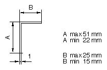
| Workpieces Dimensions | Aluminum L-profiles, thickness 1 mm, long side 30-50 mm, short side 20-28 mm. Max Piece length 1200 mm, minimum length 80 mm |
Contact us for further informations!